In today’s demanding industrial environments, materials that can withstand extreme temperature fluctuations are worth their weight in gold. Among advanced ceramics, zirconia stands out for its exceptional thermal shock resistance—a critical property that determines component lifespan and reliability in high-temperature applications. But how can engineers and procurement specialists verify these claims? This article explores the science behind zirconia’s thermal shock resistance and the rigorous testing methods that prove its superior performance.
Why Is Thermal Shock Resistance Critical For Industrial Materials?
Thermal shock resistance represents a material’s ability to withstand sudden temperature changes without cracking or failing. In industrial settings, this property isn’t just desirable—it’s essential for operational continuity and safety.
When materials experience rapid temperature changes, thermal gradients develop across their structure. These gradients create differential expansion or contraction, generating internal stresses that can lead to catastrophic failure. For high-value components in critical applications, such failures translate directly to production downtime, safety hazards, and significant replacement costs.
Zirconia ceramics demonstrate remarkable resilience against these thermal stresses compared to other engineering materials. While metals may deform plastically under thermal stress, and many ceramics crack immediately, properly engineered zirconia can withstand temperature differentials of hundreds of degrees Celsius.
Table 1: Economic Impact of Material Failure Due to Thermal Shock
| Industry Sector | Average Downtime Cost ($/hr) | Typical Replacement Time | Total Impact per Failure Event |
|---|---|---|---|
| Glass Manufacturing | $15,000 – $25,000 | 24-48 hours | $360,000 – $1,200,000 |
| Steel Production | $30,000 – $50,000 | 12-36 hours | $360,000 – $1,800,000 |
| Aerospace Components | $50,000 – $100,000 | 48-72 hours | $2,400,000 – $7,200,000 |
| Power Generation | $40,000 – $80,000 | 24-96 hours | $960,000 – $7,680,000 |
| Semiconductor Processing | $20,000 – $40,000 | 8-24 hours | $160,000 – $960,000 |
The economic impact of selecting materials with superior thermal shock resistance extends beyond immediate replacement costs. Extended component lifespans, reduced maintenance intervals, and improved process reliability all contribute to a compelling return on investment, particularly in energy-intensive industries where thermal cycling is unavoidable.
What Makes Zirconia Uniquely Resistant To Thermal Shock?
Zirconia’s exceptional thermal shock resistance stems from a combination of intrinsic material properties and engineered microstructural features.
At the heart of zirconia’s thermal shock resistance lies its relatively low thermal conductivity (2-3 W/m·K) compared to other ceramics like alumina (20-30 W/m·K). This property slows heat transfer through the material, reducing the severity of thermal gradients during rapid temperature changes.
Even more significant is zirconia’s unique transformation toughening mechanism. When properly stabilized with oxides like Y₂O₃, MgO, or CeO₂, zirconia undergoes a stress-induced phase transformation from tetragonal to monoclinic structure. This transformation is accompanied by a volume expansion that creates compressive stresses around developing microcracks, effectively arresting crack propagation.
Table 2: Key Material Properties Affecting Thermal Shock Resistance
| Property | Zirconia (YSZ) | Alumina | Silicon Carbide | Silicon Nitride |
|---|---|---|---|---|
| Thermal Conductivity (W/m·K) | 2-3 | 20-30 | 120-170 | 15-30 |
| Thermal Expansion (10⁻⁶/°C) | 10-11 | 7-8.5 | 4-5 | 3-3.5 |
| Elastic Modulus (GPa) | 200-210 | 350-400 | 380-450 | 280-320 |
| Fracture Toughness (MPa·m½) | 6-15 | 3-5 | 3-4 | 5-8 |
| Thermal Shock Parameter R (°C) | 160-350 | 80-150 | 100-300 | 300-700 |
Different stabilizers impart varying degrees of thermal shock resistance. Yttria-stabilized zirconia (YSZ) offers excellent mechanical properties but moderate thermal shock resistance. Magnesia-stabilized zirconia provides superior thermal shock resistance but lower mechanical strength. Ceria-stabilized zirconia represents a promising middle ground, with recent research showing thermal shock resistance improvements of up to 30% compared to traditional YSZ.
Microstructural engineering further enhances zirconia’s thermal performance. Controlled grain size (typically 0.3-0.5 μm), optimized porosity (3-5%), and uniform phase distribution all contribute to superior thermal shock behavior. The theoretical limits of zirconia’s thermal shock resistance continue to be pushed through advanced manufacturing techniques and compositional innovations.
Which Standard Test Methods Quantify Thermal Shock Resistance?
Several standardized testing protocols have been developed to quantify thermal shock resistance, each with specific advantages and limitations.
ASTM C1525 represents the most widely accepted water quench method for evaluating thermal shock resistance. This test involves heating ceramic specimens to predetermined temperatures, then rapidly quenching them in room-temperature water. The critical temperature difference (ΔTc) at which strength degradation begins provides a quantitative measure of thermal shock resistance. For premium zirconia grades, ΔTc values typically range from 250°C to 350°C, significantly higher than most engineering ceramics.
European standards like DIN EN 820-3 employ thermal cycling approaches, where specimens undergo repeated heating and cooling cycles of specified rates and temperature ranges. This method better simulates real-world conditions where components experience multiple thermal cycles throughout their service life.
Table 3: Comparison of Standard Thermal Shock Testing Methods
| Test Method | Standard | Key Parameters | Advantages | Limitations | Best For |
|---|---|---|---|---|---|
| Water Quench | ASTM C1525 | ΔTc, Residual Strength | Quick, reproducible, clear pass/fail | Extreme conditions, may not reflect real use | Comparative material evaluation |
| Thermal Cycling | DIN EN 820-3 | Cycles to failure, Strength degradation rate | Better simulates service conditions | Time-consuming, requires more specimens | Lifetime prediction |
| Air Quench | JIS R1618 | ΔTc, Crack initiation | Moderate severity, controlled cooling | Less standardized internationally | Components with moderate thermal gradients |
| Infrared Heating | Non-standardized | Temperature gradient, Crack propagation | Precise control, real-time monitoring | Specialized equipment, complex analysis | Research and development |
| Laser Shock | Non-standardized | Local damage, Crack threshold | Localized thermal stress, high precision | Limited sample area, specialized equipment | Components with thermal hot spots |
Infrared thermography has emerged as a powerful analytical tool for thermal shock testing. By capturing real-time temperature distributions across a specimen during thermal shock events, researchers can identify stress concentration points and optimize material compositions accordingly.
Acoustic emission techniques provide valuable insights into the progression of thermal shock damage. By detecting and analyzing ultrasonic waves generated during microcrack formation, engineers can monitor damage evolution in real-time, even before visible cracks appear.
When selecting a testing method, consider your application requirements carefully. Water quench tests provide clear pass/fail criteria but represent extreme conditions. Thermal cycling better simulates gradual degradation in many industrial environments. For critical applications, a combination of testing approaches offers the most comprehensive performance assessment.
How Do Advanced Laboratory Tests Simulate Real-World Conditions?
Beyond standardized tests, advanced laboratory methods provide deeper insights into zirconia’s thermal shock behavior under conditions that more closely approximate real-world applications.
Laser thermal shock testing represents the cutting edge in thermal shock simulation. By directing high-intensity laser beams at specific areas of a zirconia specimen, researchers can create precisely controlled thermal gradients and heating rates. This technique allows for the evaluation of localized thermal shock effects, particularly relevant for components with complex geometries or those exposed to concentrated heat sources.
Plasma jet systems generate extreme thermal conditions that simulate environments like rocket engines or plasma cutting tools. These systems can produce surface temperatures exceeding 2000°C with heating rates above 1000°C/second, pushing zirconia to its performance limits.
Table 4: Advanced Thermal Shock Testing Parameters and Applications
| Testing Method | Temperature Range (°C) | Heating Rate (°C/s) | Cooling Rate (°C/s) | Thermal Gradient (°C/mm) | Primary Applications |
|---|---|---|---|---|---|
| Laser Thermal Shock | RT to 2500 | 500-5000 | 300-3000 | 100-500 | Aerospace components, Thermal barriers |
| Plasma Jet | RT to 3000 | 1000-10000 | 500-5000 | 200-1000 | Rocket nozzles, Plasma-facing components |
| Thermomechanical Fatigue | RT to 1500 | 5-50 | 5-50 | 5-20 | Engine components, Industrial furnace parts |
| Infrared Imaging | RT to 1800 | 10-100 | 10-100 | 10-50 | Quality control, Failure analysis |
| Digital Image Correlation | RT to 1200 | 1-50 | 1-50 | 1-20 | Design optimization, Strain mapping |
Thermomechanical fatigue testing combines thermal cycling with mechanical loading, replicating conditions found in applications like automotive engine components or industrial furnace parts. This approach reveals how thermal shock resistance degrades under combined thermal and mechanical stresses over thousands of cycles.
Digital image correlation techniques have revolutionized strain measurement during thermal shock events. By tracking the movement of surface patterns during heating and cooling, researchers can map strain distributions with micrometer precision, identifying vulnerable areas in component designs.
These advanced testing methods reveal that zirconia’s thermal shock performance isn’t just a material property—it’s highly dependent on component geometry, surface finish, and specific application conditions. The most effective testing approaches combine multiple methods to build a comprehensive performance profile.
What Performance Metrics Determine Superior Thermal Shock Resistance?
Several key metrics help quantify and compare the thermal shock resistance of different zirconia grades and compositions.
The critical temperature difference (ΔTc) represents the maximum temperature change a material can withstand without significant strength degradation. For engineering applications, this parameter directly translates to operational safety margins. Premium zirconia grades achieve ΔTc values up to 350°C, while conventional ceramics typically range from 100-200°C.
The thermal shock resistance parameter (R) provides a more theoretical approach, calculated as:
R = σ(1-ν)/Eα
Where σ is strength, ν is Poisson’s ratio, E is elastic modulus, and α is the thermal expansion coefficient. Higher R values indicate better thermal shock resistance. This parameter allows engineers to predict thermal shock behavior based on fundamental material properties.
Thermal cycling lifetime evaluates how many heating-cooling cycles a material can endure before failure. This metric is particularly relevant for components in intermittent service. Premium zirconia grades can withstand thousands of moderate thermal cycles (ΔT ≈ 200°C) before showing significant degradation.
Residual strength ratio—the percentage of original strength retained after thermal shock—provides insight into damage tolerance. Materials with gradual strength degradation offer more predictable service life than those exhibiting catastrophic failure.
Statistical analysis using Weibull distributions helps account for the inherent variability in ceramic performance. Rather than single-point values, Weibull analysis provides reliability predictions at different confidence levels, essential for risk assessment in critical applications.
How Do Different Zirconia Grades Compare In Thermal Shock Tests?
Not all zirconia ceramics offer equal thermal shock resistance. Understanding the performance differences between various grades is essential for appropriate material selection.
Fully stabilized zirconia (FSZ) contains sufficient stabilizer (typically 8 mol% Y₂O₃) to maintain a cubic crystal structure across all temperatures. While chemically stable, FSZ lacks the transformation toughening mechanism that enhances thermal shock resistance. In water quench tests, FSZ typically shows ΔTc values around 150-200°C.
Partially stabilized zirconia (PSZ), containing 3-4 mol% Y₂O₃, offers significantly improved thermal shock resistance with ΔTc values of 250-300°C. The presence of transformable tetragonal precipitates within a cubic matrix provides an optimal balance of mechanical properties and thermal shock resistance.
Table 5: Thermal Shock Performance Comparison of Zirconia Grades
| Zirconia Grade | Composition | Critical Temperature Difference (ΔTc, °C) | Thermal Cycles to 25% Strength Loss | Residual Strength Ratio After 10 Cycles | Cost Factor | Best Applications |
|---|---|---|---|---|---|---|
| FSZ | 8 mol% Y₂O₃ | 150-200 | 50-100 | 0.60-0.70 | 1.0 | Chemical processing, Oxygen sensors |
| PSZ | 3-4 mol% Y₂O₃ | 250-300 | 200-500 | 0.75-0.85 | 1.2-1.5 | Thermal barriers, Pump components |
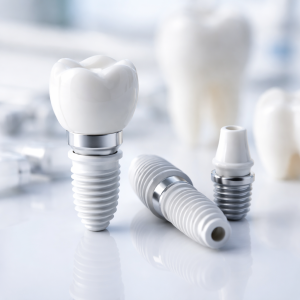
| TZP | 2-3 mol% Y₂O₃ | 200-250 | 100-300 | 0.70-0.80 | 1.5-2.0 | Mechanical components, Dental implants |
| Ce-TZP | 12 mol% CeO₂ | 300-350 | 500-1000 | 0.80-0.90 | 2.0-2.5 | Extreme thermal cycling applications |
| ATZ | 20% Al₂O₃ + Y-TZP | 250-300 | 400-800 | 0.75-0.85 | 1.8-2.2 | Cutting tools, Wear components |
Tetragonal zirconia polycrystals (TZP) contain even lower stabilizer content (2-3 mol% Y₂O₃), maximizing transformation toughening effects. While offering exceptional mechanical strength, standard TZP shows moderate thermal shock resistance due to its relatively high elastic modulus. However, specialized TZP formulations with engineered grain boundaries can achieve ΔTc values approaching 350°C.
Zirconia-based composites represent the frontier of thermal shock resistance. Zirconia-toughened alumina (ZTA) and alumina-toughened zirconia (ATZ) leverage the complementary properties of both ceramics. ATZ composites containing 20% alumina have demonstrated thermal cycling lifetimes up to 300% longer than monolithic zirconia.
Nanostructured zirconia, with grain sizes below 100 nm, exhibits remarkable thermal shock behavior due to enhanced grain boundary sliding and crack deflection mechanisms. Recent research has achieved ΔTc improvements of 40-50% compared to conventional microstructured zirconia.
Which Industries Benefit Most From Zirconia’s Thermal Properties?
Zirconia’s exceptional thermal shock resistance makes it invaluable across numerous high-temperature industries.
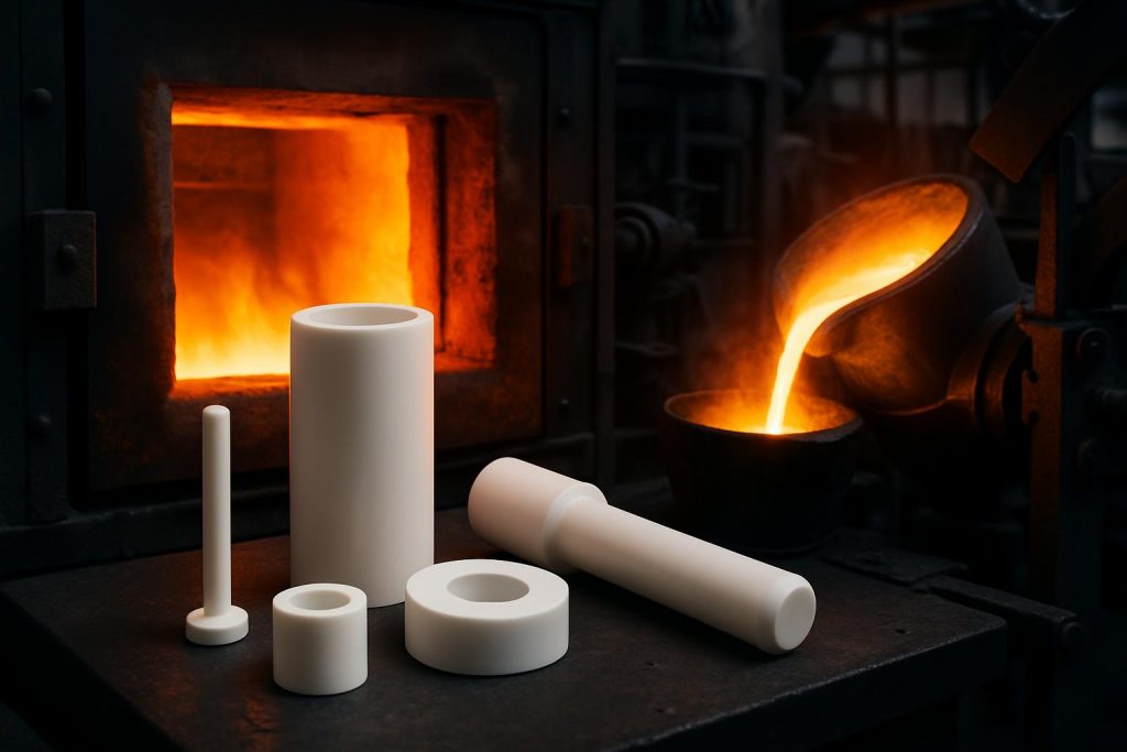
In metallurgical applications, zirconia components withstand the extreme thermal gradients encountered in molten metal handling. Thermocouple protection tubes, crucibles, and ladle nozzles benefit from zirconia’s ability to survive repeated immersion in molten metals at temperatures exceeding 1500°C.
The glass manufacturing industry relies heavily on zirconia components for handling molten glass. Plungers, stirrers, and feeder parts made from zirconia can withstand the thermal cycling inherent in glass forming operations, significantly outlasting traditional materials.
Aerospace applications leverage zirconia’s thermal properties in thermal barrier coatings and structural components for propulsion systems. The material’s low thermal conductivity and high-temperature stability make it ideal for protecting underlying metal structures from extreme heat.
In energy generation, solid oxide fuel cells (SOFCs) utilize yttria-stabilized zirconia as an electrolyte material. The thermal cycling durability of zirconia enables these systems to withstand thousands of startup-shutdown cycles without degradation.
Automotive emission control systems employ zirconia-based oxygen sensors that must function reliably through countless thermal cycles as exhaust temperatures fluctuate. The material’s combination of ionic conductivity and thermal shock resistance makes these critical components possible.
How To Implement Thermal Shock Testing In Quality Control?
Implementing effective thermal shock testing in your quality control process ensures consistent performance of zirconia components in demanding applications.
Establish a comprehensive testing protocol that reflects your specific application conditions. Rather than adopting generic standards, consider customizing test parameters such as temperature ranges, heating/cooling rates, and cycle counts to match your operational environment.
When evaluating supplier qualifications, request detailed thermal shock performance data, including testing methodologies and statistical analysis. Premium suppliers should provide Weibull statistics rather than simple average values, giving you insight into reliability across production batches.
Develop a strategic sampling plan based on statistical quality control principles. For critical components, consider implementing both lot acceptance testing (evaluating a sample from each production batch) and periodic surveillance testing (more comprehensive evaluation at scheduled intervals).
Set performance thresholds based on application requirements rather than material capabilities. A component that passes standard tests may still fail in your specific application if the testing conditions don’t adequately represent your operational environment.
Establish clear correlations between laboratory test results and field performance through systematic data collection and analysis. This feedback loop allows continuous refinement of testing protocols and acceptance criteria, ensuring that laboratory evaluations accurately predict real-world performance.
FAQ Section
Q1: How does zirconia’s thermal shock resistance compare to other engineering ceramics?
Zirconia significantly outperforms most engineering ceramics in thermal shock resistance. Compared to alumina, zirconia’s thermal shock parameter (R value) is typically 30-50% higher, primarily due to its lower elastic modulus and unique transformation toughening mechanism. While silicon carbide offers higher thermal conductivity, zirconia’s lower conductivity can actually be advantageous in certain applications by slowing heat transfer rates. At extreme temperatures (>1500°C), specialized silicon carbide and silicon nitride ceramics may perform better. Zirconia’s true advantage lies in its combination of good thermal shock resistance with excellent mechanical strength and chemical stability—a comprehensive performance profile unmatched among engineering ceramics.
Q2: What is the difference between water quench and air quench thermal shock testing?
Water quench and air quench testing represent different severity levels of thermal shock evaluation. Water quench testing (like ASTM C1525) involves immersing samples directly from high temperature into room-temperature water, creating extreme temperature gradients and cooling rates (>300°C/second)—representing “worst-case scenario” thermal shock. Air quench testing uses forced air flow to cool samples at more moderate rates (typically <100°C/second), better approximating many real industrial environments. Water quench tests primarily evaluate a material’s ultimate thermal shock resistance and catastrophic failure threshold, while air quench tests are better suited for assessing progressive damage and long-term thermal cycling performance. The choice between testing methods should be based on target application environment and failure mode analysis.
Q3: Can thermal shock resistance of zirconia be improved through compositional modifications?
Yes, zirconia’s thermal shock resistance can be significantly enhanced through various compositional adjustments. Adding 2-3 mol% ceria (CeO₂) can enhance the transformation toughening effect, improving the thermal shock parameter (R value) by 20-30%. Aluminum doping (forming ATZ composites) increases thermal conductivity, reducing temperature gradients. Complex stabilization with rare earth elements like lanthanum and yttrium creates more sophisticated microstructures with improved thermal cycling lifespans. Recent research shows that adding nano-scale SiC whiskers can form self-healing microcrack networks that absorb strain energy during thermal cycling. However, any compositional modification requires balancing effects on mechanical strength, phase stability, and chemical inertness, necessitating optimization for specific applications.
Q4: How does specimen size affect thermal shock test results?
Specimen size significantly influences thermal shock test results—a critical consideration when evaluating and comparing data. Larger specimens typically exhibit lower critical temperature difference (ΔTc) values because they develop greater temperature gradients and internal stresses during thermal shock. ASTM standards typically specify 10×10×50mm bar specimens, but many studies and industry tests use different geometries. Specimen thickness is particularly crucial—each additional millimeter of thickness can reduce critical temperature difference values by 5-8%. Additionally, specimen surface condition (roughness, microcracks) significantly affects results. To ensure meaningful comparisons, standardized specimen dimensions should be used, or size effect correction factors applied, especially when evaluating test data from different sources.
Q5: What non-destructive testing methods can detect thermal shock damage in zirconia components?
Several non-destructive testing (NDT) methods effectively detect thermal shock damage in zirconia components. Ultrasonic testing is among the most common, identifying internal microcracks and phase transformation zones, particularly with high-frequency (>15MHz) probes. Acoustic emission monitoring captures crack formation and propagation in real-time during thermal shock events. X-ray computed tomography (CT) provides three-dimensional visualization of microstructural changes with resolution down to the micron level. Raman spectroscopy analysis detects phase transformation regions, particularly tetragonal to monoclinic transitions. Advanced infrared thermography combined with artificial intelligence analysis rapidly identifies subsurface damage. Selection among these NDT methods should be based on component size, geometry, anticipated damage types, and detection sensitivity requirements.